UML Use Case Diagrams: Purpose, Elements, and Relationships
UML Use Case Diagrams are essential tools for capturing the dynamic aspects of a system. They are primarily used during requirement analysis to identify functionalities, actors, and their interactions. Here’s an in-depth guide on use case diagrams’ purpose, components, and relationships.
Purpose of Use Case Diagrams
Use case diagrams serve multiple purposes, including:
- Gathering Requirements: Highlight internal and external influences on the system.
- Providing an Outside View: Offer a high-level perspective of the system’s functionalities.
- Identifying Influencing Factors: Distinguish between actors and use cases.
- Modeling Interactions: Showcase how actors interact with use cases and their relationships.
How to Draw a Use Case Diagram
Step 1: Identify Core Components
To create a meaningful use case diagram, you must identify the following:
- Functionalities: Represented as use cases (e.g., actions or services).
- Actors: Entities interacting with the system (users, devices, or other systems).
- Relationships: Define dependencies and interactions between actors and use cases.
Step 2: Follow Best Practices
- Use meaningful names for use cases and actors.
- Clearly depict relationships (e.g., associations, include, extend).
- Avoid overcrowding with unnecessary relationships.
- Use notes to clarify important points if required.
Step 3: Iterative Refinement
Begin with a high-level design, and refine it repeatedly to capture all functionalities and interactions effectively.

Components of a Use Case Diagram
- Actors:
- Represent users or systems interacting with the application.
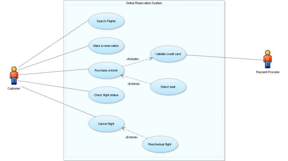
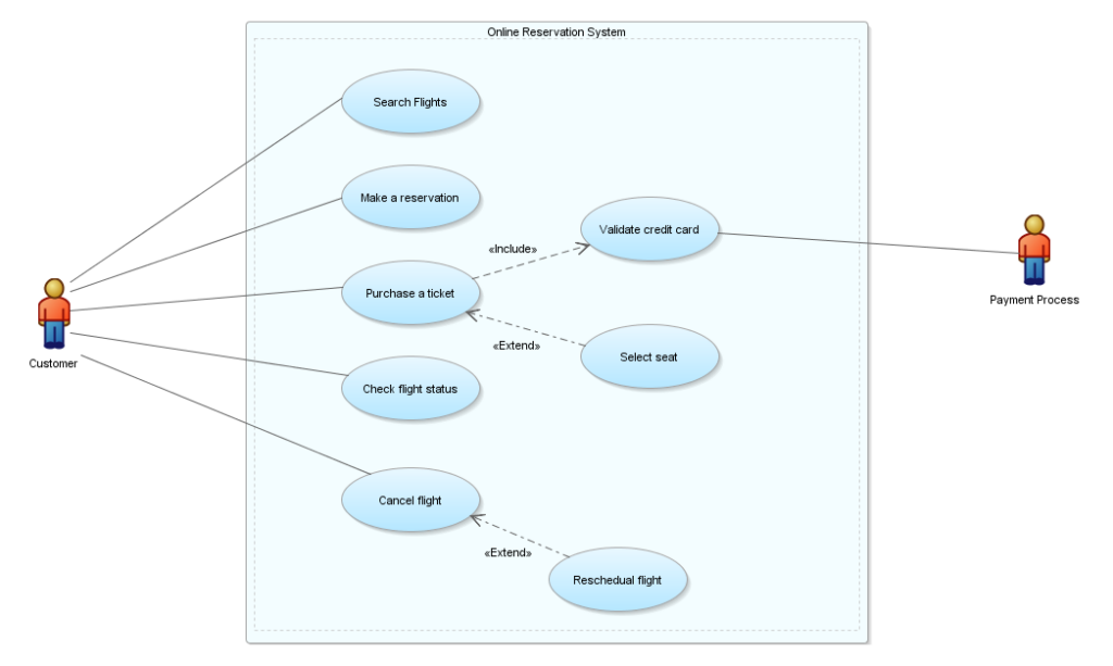
- Example: A Customer interacting with an online reservation system.
- Use Cases:
- Represent functionalities provided by the system.
- Example: Search flight, Make a reservation.
- Relationships:
- Association: Connects actors to use cases.
- Include: Reuses functionality of another use case.
- Extend: Extends the behavior of a base use case.
- Generalization: Defines parent-child relationships.
- System Boundaries:
- Represented by a rectangular box to delineate the system’s scope.
Use Case Relationships
- Association:
Defines the interaction between an actor and a use case.
Example: A Customer associating with Purchase a ticket. - Include Relationship:
One use case reuses another’s functionality.
Example: Purchase a ticket includes Validate credit card. - Extend Relationship:
Adds additional behavior to a base use case.
Example: Reschedule flight extends Cancel flight. - Generalization Relationship:
Defines a hierarchical relationship where a child inherits from a parent.
Example: A User generalizes to Admin and Guest.
Example: Order Processing System
Consider an online reservation system with the following elements:

Applications of Use Case Diagrams
- Requirement Analysis: Helps understand system functionality and dependencies.
- High-Level Design: Provides an overview of system context and interactions.
- Reverse engineering helps in analyzing existing systems.
- Forward Engineering: guides system development and implementation.
Conclusion
Use case diagrams are invaluable for capturing functional requirements and modeling system interactions. By following best practices and refining your diagrams iteratively, you can effectively document and communicate system requirements.
Would you like detailed examples or guidance on creating use case diagrams for specific applications? 😊
https://agohar.me/blog/understanding-association-aggregation-and-composition/
